MIL-HDBK-61A: Configuration Identification
< Previous | Contents | Next >
5.4 Configuration Documentation
The term configuration documentation characterizes the information that defines the performance, functional and physical attributes of a product. As described in EIA Standard 649, all other product documentation (such as operation and maintenance manuals, illustrated parts breakdowns, test plans and procedures) are based on and relate to information in the configuration documentation. The configuration documentation associated with each CI provides the basis for configuration control [See Section 6], logistics support, post-deployment software support, and re-procurement.
Acquisition reform has made a significant change in the types of configuration documents used to specify configuration items and on the baselining and configuration control of configuration documentation. Since the Government now specifies performance and, in most cases, leaves design solutions to the contractor, the Government determines the system product structure level at which to specify, baseline and control item performance and the specification type to be used. Below this level the contractor chooses the types of documentation to use. [Details 5.4.1 through 5.4.4]
The selection of the appropriate specification document types is dependent upon a number of factors such as the maturity of the item, and the context and environment in which it must operate. The new order of precedence defined by DoD policy strongly indicates preference for the use of existing commercial products, wherever possible, and the choice of products meeting Performance rather than Detail Specifications. [Details: 5.4.2, Activity Guide: Table 5-5.]
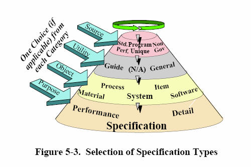
Program Unique Specifications, of both a performance and detailed nature, are at the bottom of the preference hierarchy and are used when the other choices are not available or applicable. Nonetheless, acquisition programs dealing with the development of new systems will continue to see the use of program unique specifications where the specifications are being prepared for a single system or item and have little potential for future use except for repetitive fiscal year production and spares purchases. Both the Government and contractors should seize opportunities at lower levels of the specification tree (where developed items, referred to as non-developmental items (NDI) may be used) to select higher preference specification types, and to specify only performance and interface requirements rather than design solutions in those specifications, whenever possible. To aid in understanding the array of various designations used to identify specifications, Figure 5-3, categorizes the specification document types, as follows:
-
Source (Non-Government, Commercial, Federal, Military, Program Unique) - category indicates the standardization/specification domain of the document; [Detail: Activity Guide: Table 5-4]
-
Utility (General, Generic or Guide) if applicable- relates to the characteristic of the documents that facilitates standardization by providing "boilerplate" or templates for classes of items with largely common requirements. This category applies only to those documents where these characteristics are applicable. [Detail: Activity Guide: Table 5-5]
-
Object (System, Item, Software, Material, Process) - represents the type of CI object in MIL-STD-961D, Appendix A that a specification is intended to define. The objects are not restricted to use with program unique specifications; they are applicable for use with the other source categories as well. They replace the MIL-STD-490 categories, e.g., prime item, critical item, inventory item, etc. [Detail: Activity Guide: Table 5-6]
-
Purpose (Performance or Detail) - distinguish between performance and detail specifications. Their content and format are delineated in MIL-STD-961D. Performance specifications define requirements and constraints for a system or CIs entering the engineering and manufacturing development phase or being acquired at a performance level. Detail specifications define requirements and a specific design for CIs being acquired during a production, deployment and operational support phase. [Detail: Activity Guide: Table 5-7]
The activity guides for Specifications, Tables 5-5 through 5-7 follow.
Activity Guide: Table 5-5. Order of Preference for Specifications
Activity Guide: Table 5-4. Specification Types Categorized by Source
This table describes various standardization and specification domains in which a specification may originate. This category is part of a string comprising the specification type. [See Fig. 5-3]
Activity Guide: Table 5-5. Specification Types Categorized by Utility
This table describes a category of specifications that facilitate standardization by providing "boilerplate" or templates for classes of items with largely common requirements. This category applies only to those documents where these characteristics are applicable. This category is part of a set of categories, which comprise the specification type. [See Fig. 5-3]
Activity Guide: Table 5-6. Specification Types Categorized by Object
This table describes the type of CI "objects" that a specification is intended to define. This category is part of a string of categories which comprise the specification type. [See Fig. 5-3]
Activity Guide: Table 5-7. Specification Types Categorized by Purpose
This table describes the categories that indicate the intent of the specification, i.e., distinguish between performance and detail specifications. This category is part of a set of categories that comprise the specification type. [See Fig. 5-3]
The requirements of the functional and allocated baselines [See 5.5] are basically design constraints on the development contractor. The design solution evolves from the contractor's design and development process during the engineering and manufacturing development phase of the life cycle. This process essentially converts the performance requirements of the baseline specification into a specific product definition that can be manufactured to produce a hardware item or compiled to produce a software item. It is documented in design documentation for the hardware and the software comprising each CI.
For hardware, the design documentation may be in the form of engineering drawings and associated lists, and the material and process documents that are referenced by the drawings. In the current information environment, the primary design documentation source may be in the form of two or three-dimensional engineering models. In that case, a drawing is simply a two dimensional view of a model that exists in a data base file. Various models and product modeling tools may be employed. Engineering drawings may or may not exist as a central part of the product manufacturing process, depending on the product and the degree of automation technology employed.
In an automated development and production environment, an item is designed on the engineer's workstation, manufacturing instructions are added at the manufacturing planner's workstation and the results are fed directly to automated machinery that produces the item. Commonly, items are designed using computer-aided design tools (CADAM, CATIA, AUTOCAD, etc.) and engineering drawings are plotted for human checking and review. Where engineering drawings are required as a contract deliverable, they should be delivered in place, in a CALS compliant format.
For software, the design evolves through a software engineering process, using a variety of integrated tools, often called the software engineering environment, e.g., Computer-aided software engineering (CASE). The process results in computer based versions of documentation, source, and executable code for every CSCI. [See Activity Guide: Table 5-9. Software Documentation.] The process the contractor employs to manage the automated software documentation (e.g., software library management and archiving) is similar to the process used to manage automated hardware documentation, although different tools may be employed. Upon close examination, it is fundamentally the same process used to manage the files, which contain software code. The same business rules apply to both software and documents in terms of their identification and relationships to other entities. [Section 9]
Acquisition reform has essentially freed the contractor to evolve the most efficient methodology for evolving the design solution in a way that is appropriate to the scope and complexity of the particular product or product line. It is important for the acquisition program manager to recognize that there will be a great deal of diversity in the methodologies employed by various contractors, although there will also tend to be a great deal of similarities within given industry segments such as aerospace. Where it is necessary for the Government to capture the detailed design the contractor may map the information in his internal databases to the appropriate fields of the Government's CM AIS. [Section 7]
The developmental configuration documentation to be managed by the development contractor consists of the design and technical data under the contractor's internal control. Some of this data may transition to Government configuration control and be designated as the Government Product Baseline; some of it may remain under Contractor configuration control and be designated as Contractor Product Baseline. [5.5.1, 5.5.2] The developmental configuration management process implemented by the development contractor consists of a formal process to control the documentation and repositories containing the elements of the developmental configuration. The contractor's engineering release system [Details: 5.7] and engineering release records are an important part of this management process. Each and every version of all elements of the developmental configuration released, for whatever purpose, should be maintained, along with the reasons the version was released, and the rationale for superseding the previous version.
Tables 5-8 and 5-9 provide detailed information concerning the documentation used to document the design solution.
Table 5-9 also contains a complete set of software documents that are used for planning, system and software requirements analysis, software integration and testing, software product definition, operation and maintenance in addition to design description. Several software design description documents can evolve from earlier versions used to support one or more of these other functions. The Government needs access to some of these documents to the extent necessary for logistic support and software maintenance during the operational support period. This activity guide therefore addresses the documentation that can evolve over the full life cycle of a system/CSCI. Detailed design documents for the CIs and CSCIs that the Government will support will be made accessible from a Government repository (e.g., JEDMICS). Meta-data concerning these documents will be available from CM AIS provided that the information that the Government requires the contractor to load into these systems is specified in the contract. [Section 7, Section 9]
Activity Guide: Table 5-8. Engineering Drawings and Associated Lists
Activity Guide: Table 5- 9. Software Documentation
Life Cycle processes in accordance with ISO/IEC 12207.
Tailoring guidance: For a SW product embedded in a system, all life cycle process activity should be considered, relevant activities should be applied and tailored for each subsystem or configuration item; for a standalone software project, the system activities may not apply.
Document types in accordance with Joint Standard 016 and ISO/IEC 12207
ISO/IEC 12207 emphasizes that the documentation is variable and tailorable to fit the project. Other documentation that meets the intent is acceptable.
Contractor design release baseline; alias development configuration, release record
Coding and testing the SW
May be updated SDD, IDD, DBDD
For correct application of this information, see NOTE on Contents page